



Processing & BIM
MEP modelling: building services in existing buildings, from the point cloud
Pipes, ducts, routes and plant as an as-built model, so that your services design can start immediately instead of spending weeks measuring first.
What an MEP as-built model is
An MEP as-built model represents the building services as components: pipework with its route and diameter, ventilation ducts with their cross-sections, cable routes, distribution boards, generating plant and terminal units. Metrika360 captures the existing installation by 3D laser scanning and models the services as a discipline model in its own right, native in Revit or vendor-neutral as IFC.
We treat pure MEP projects as a discipline of their own, separate from building modelling: here it is not about walls and areas but about the plant room, the central unit, the distribution network. What gets modelled is what your design needs, at the depth your design specifies.
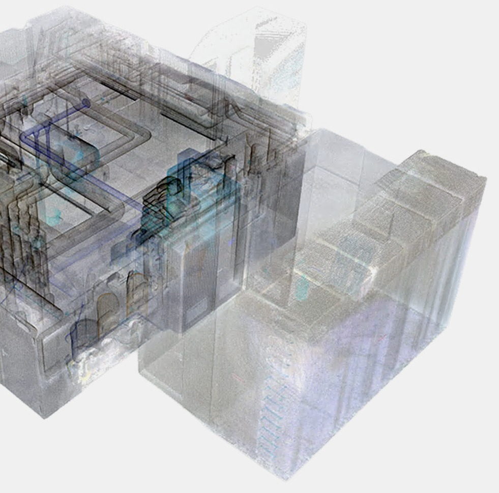
The level of detail comes from your design, not from our catalogue
On MEP projects the services designer decides what belongs in the model and how finely: which trades, which areas, whether only the installation that stays or also what will be stripped out, whether supports and valves individually or as a run. We model to your specification and adopt your naming and system logic, so that the model lives on inside your design environment rather than beside it.
The standardised term for this is the level of information need: the information requirement is determined by the intended use, not by a blanket level of detail. That is exactly what this paragraph means.
Anyone without a specification yet gets a proposal from us based on the task, but the decision stays with the designer. The model is your tool, not our product scheme.
Why MEP is different from architecture
A wall stands free in the room; a pipe hardly ever does. Three things make MEP capture a discipline of its own:
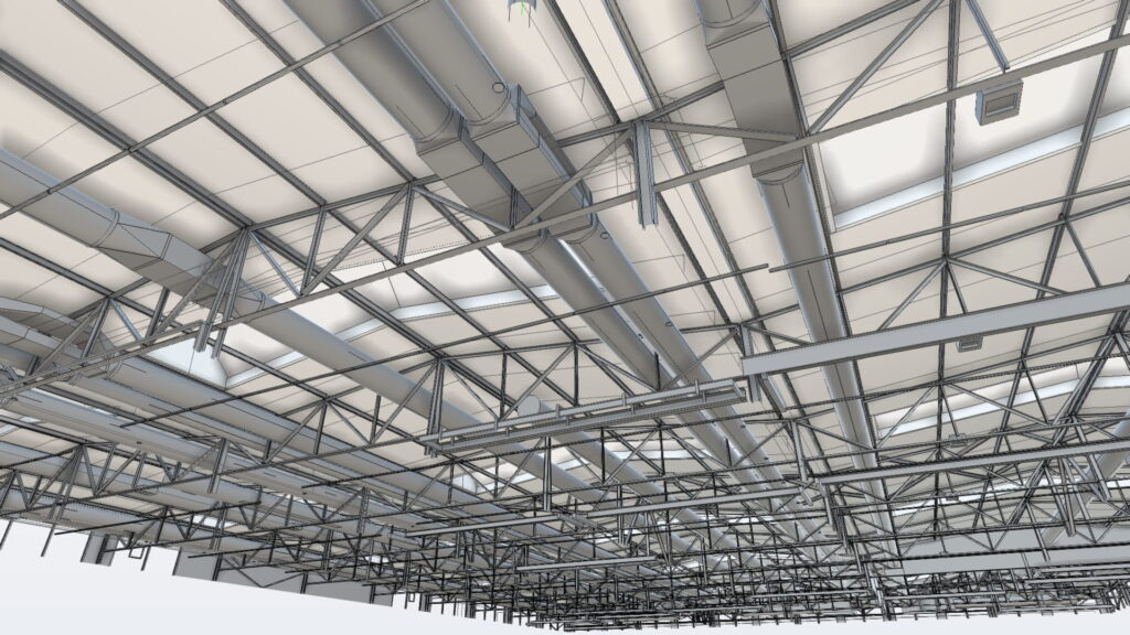
The services conceal themselves. Pipes lie in bundles, behind ducts, under fittings. A stationary scanner sees the front layer and casts shadows on everything behind it. We therefore combine devices: the FARO scanner terrestrially for the plant room, the body-worn NavVis VLX for areas and storeys, and the hand-held NavVis MLX where it gets tight — between, behind and underneath the installations, where neither tripod nor backpack can reach.
What is measured is the outer face. The scan supplies the diameter over the insulation, not the nominal bore of the pipe underneath. Confusing the two leads to wrong sizing. We take nominal bores from labelling and documents; where both are missing, the model states the measured outer dimension, marked as such.
The density is different. A plant room contains more components in fifty square metres than a whole office storey. The effort follows the number of components, not the area, which is why MEP is agreed per area rather than as a blanket price per square metre.
Typical projects
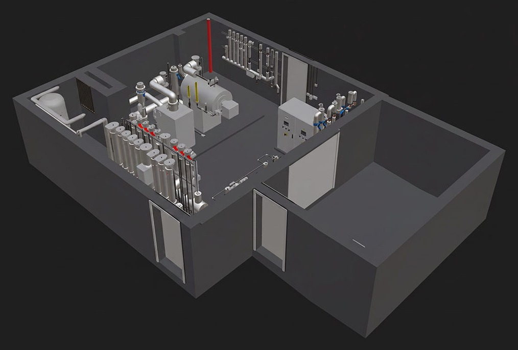
Plant rooms and boiler houses. Replacing the generating plant, converting to heat pumps, the new central unit: whether the new equipment fits into the old room is decided by installation areas, connection points, pipe routes and transport routes. The model answers that at the desk, before anything is ordered.
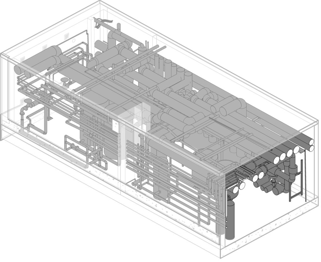
Pool and water treatment plant. A swimming pool basement is among the denser MEP spaces: water treatment, filters, pumps and pipework in a confined space, and every refurbishment of the pool begins precisely down there. We capture the plant level completely, including where no tripod fits between the pipes any more, and deliver the discipline model the refurbishment is designed on.
Sprinkler and fire-fighting systems in existing buildings. The existing network and the hall structure as the basis for extension or redesign, with routes, trusses and obstructions the new design has to work around.
Ventilation ducts in industrial halls. Duct cross-sections, route layouts and spare space above production areas, as a discipline model for redesign and for clash detection of the new design against the existing installation.
Plant engineering and extension. Planning new equipment into a running production line, connected to what is demonstrably there.
Who we do this for
MEP design practices. You get the existing installation as a discipline model in your own system and start straight into sizing. Your own survey in the plant room becomes unnecessary, and with it the site visits, the re-measuring and the assumptions that take revenge later.
Installers and plant contractors. Heating, ventilation, sprinkler contractors: anyone tendering in existing buildings calculates on measured routes instead of walk-through photographs, and anyone prefabricating fabricates against what is there.
Industry and operators. Works services, media supply, production infrastructure: the documented actual state as a basis for extension, maintenance and the next tender.
The time gained is the real reason to buy
A manual survey in a crowded plant room takes days, remains incomplete and ties up precisely the specialists who ought to be designing. Our capture takes one visit, even while the building is in use, and the model arrives finished in your design environment. The start of design therefore moves weeks forward, and the second trip because a dimension was missing at the site visit disappears structurally: whatever the point cloud contains can be re-measured at any time without anyone going back down into the basement.
And where the basement has no windows, the walkable virtual tour from the same capture helps.
Light in the dark: windowless plant rooms
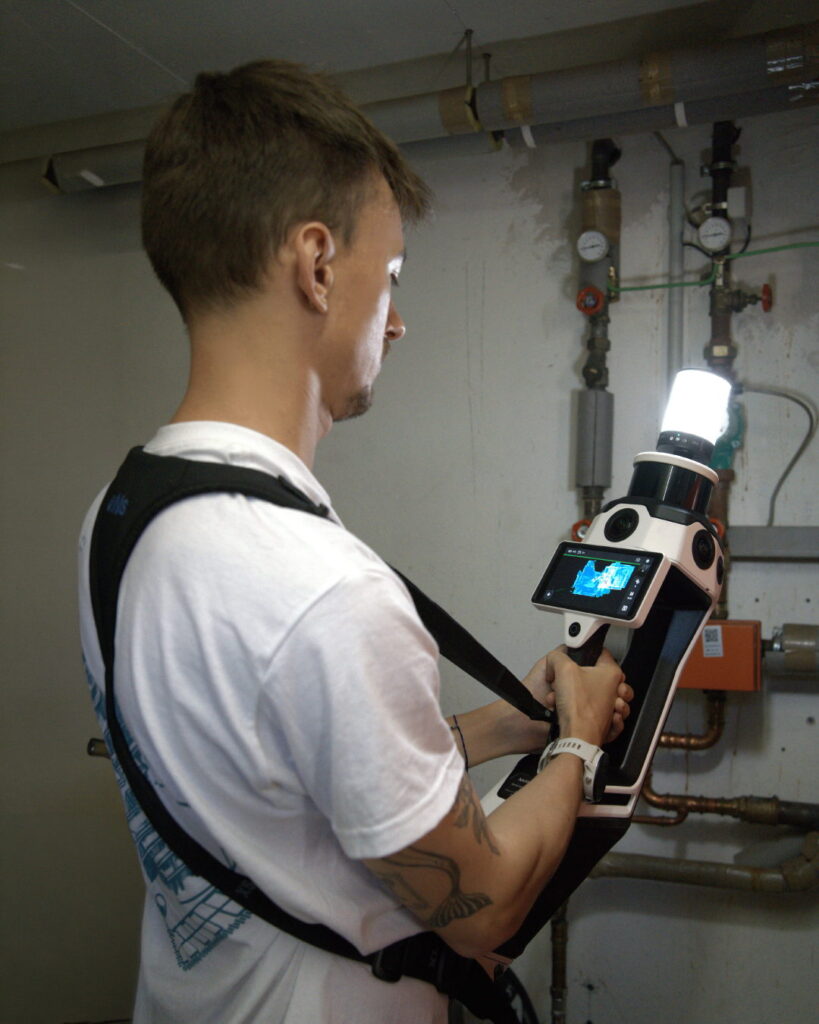
The scanner captures the geometry even in pitch darkness; light is irrelevant to the laser. But plant rooms should not only be measured in the result but also seen: coloured point cloud, panoramas, walkable tour. For that we light unlit areas mobile during the capture, with the Halo system from Bushman Light, which accompanies the operator with even all-round light instead of casting hard shadows from a site lamp. The result: a tour in which you can see what hangs from the ceiling even in a windowless basement.
What the scan does not deliver, and how we handle it
The scan captures geometry. Medium, direction of flow, nominal bore under the insulation and the condition of a plant item are not in the point cloud. This information comes from labelling, documents or the walk-through, and in the model its origin is marked: measured, adopted or assumed. What lies behind closed ceilings and shafts we capture only if they are opened; anything else would be guesswork.
And one distinction that saves confusion: MEP modelling supplies the geometry of the services. The alphanumeric plant register — plant identification, condition assessment and the data model to DIN 276 for the operator’s duties — is the discipline of our partner AdvisoRE. Both together, from one walk-through, make the complete CAFM data foundation.
Further reading
- 3D laser scanning – the capture the discipline model grows out of
- Virtual tours – the walkable plant room from the same capture
- CAFM data foundation – where geometry and plant data come together
- BIM as-built models – the building model beside the discipline model
- Scan-to-BIM – the route from point cloud to model
Frequently asked questions about MEP modelling
Who determines how detailed the modelling is?
Your services designer. On pure MEP projects we model to the design specification: trades, areas, component depth, naming logic. Anyone without a specification yet gets a proposal based on the task, but decides for themselves.
Which trades do you capture?
Heating, cooling, ventilation, sanitary, electrical and fire-fighting services, plus conveying systems by agreement. The scope is fixed per trade and per area, not across the board.
Can you capture nominal bores?
What is measured is the outer face, on insulated pipes therefore including the insulation. We take nominal bores from labelling and documents; where both are missing, the model marks the measured value as an outside dimension. That honesty saves you wrongly sized connections.
Do you also capture above suspended ceilings and in shafts?
Only what is visible or is opened up. We make use of access panels; opening up larger areas we agree in advance. Areas that cannot be seen are marked as an assumption rather than filled in.
Does capture work in dark basements?
The measurement yes; the laser needs no light. For coloured point clouds, panoramas and the walkable tour we light unlit areas mobile during the walk-through. Whether colour and tour are part of the delivery we settle beforehand, because it affects the procedure on site.
In which system is the modelling done?
Preferably native in Revit, so that your services design carries straight on, plus IFC as a neutral format. Transfer into MEP sizing software with a Revit link is the normal case.
How fast is it?
The capture takes one visit, even while the building is in use. The modelling period we state in the quotation; for individual plant rooms we are talking days, not weeks. And any dimension still missing later comes from the archived point cloud instead of a new site visit.
Do you check the new design against the existing installation?
Yes. The services design is clash-checked in the model against the captured installation, and conflicts are documented per component before they cost money on site.