



Applications & special services
As-built data for factory and layout planning
Anyone replanning a production facility plans against what is there: column grid, doors, heights, media, machines. We supply the actual layout as a dependable basis, readable straight into your layout planning software.
What layout planning needs from the existing facility
A layout rarely fails on the concept and often on a dimension nobody checked. The hall has one column more than the drawing shows, the door is twenty centimetres lower than assumed, and the machine that is to stand there does not fit through any of the three approaches. Such points show up in the building, not in the drawing.
These five quantities decide almost every replanning exercise:
| Quantity | Why it is decisive |
|---|---|
| Column grid | Determines which installation areas are contiguous at all. In facilities that have grown over time, the grid is rarely as regular as the old drawing suggests. |
| Clear heights | Underside of truss, underside of service run, underside of crane rail: three different heights over the same floor area. For installing plant, the lowest one counts. |
| Doors and approaches | Width, height and swept path decide whether a machine can reach its place at all. The transport route is part of the planning, not of the execution. |
| Media | Where compressed air, power, water and extraction are available today determines the cost of every relocation. |
| Existing plant | The actual space required including operating, maintenance and safety areas — not the dimension from the data sheet. |
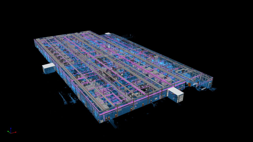
Why old drawings are particularly unreliable in production facilities
Production buildings change more often than office buildings, and they change in small steps: an additional extraction point, a moved partition, a foundation for a machine bought twelve years ago. Each of these interventions was documented, or it was not, and which is the case cannot be told from the drawing.
That is exactly where the difference lies between a survey and a well-kept drawing archive: the survey shows the state on the day of capture, with a date, and nobody has to take the drawing on trust. It is the reason a replanning project usually starts with a survey and not with opening the old file.
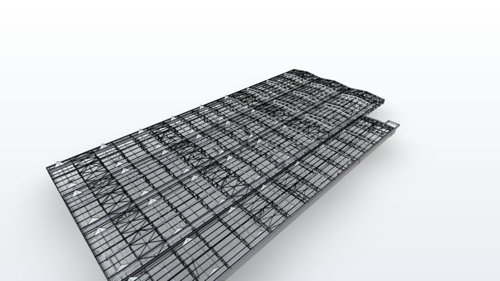
Capturing without stopping production
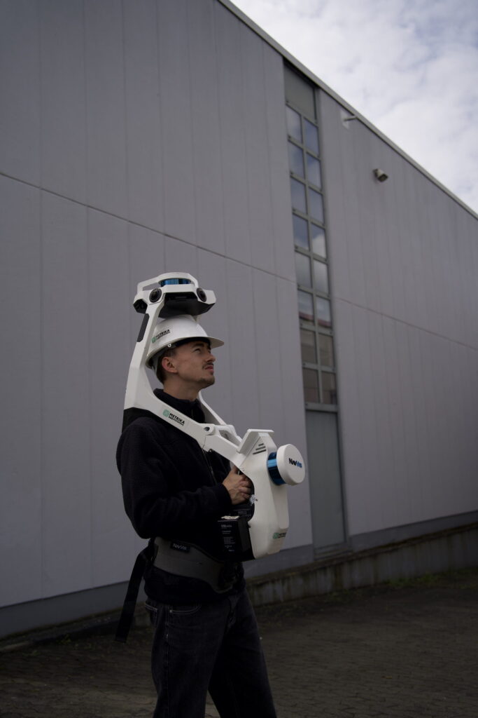
A running production line cannot be shut down for a survey, and it does not have to be. We capture halls by mobile mapping on the move, along the routes that are clear anyway. Where every millimetre counts — at a connection point or a foundation, for instance — the area is additionally captured terrestrially from the tripod and computed into the same point cloud.
Two points from practice that shape the appointment: obstructed areas are captured as they stand, and what is behind a rack is not in the model afterwards. And shift changes or shutdown periods are the most favourable capture windows, because routes are then clear that are otherwise in constant use.
The capture is georeferenced if you need it — for joining several halls into one continuous site layout that is the precondition. How that works is set out on 3D laser scanning.
What you receive, and in which format
Layout planning systems do not compute with point clouds but with areas, axes and solids. The capture therefore produces what your system actually reads:
| Result | Format | What for |
|---|---|---|
| Actual layout as a 2D drawing | DWG, DXF, PDF | Basis for layout planning: axes, columns, walls, doors, plant outlines |
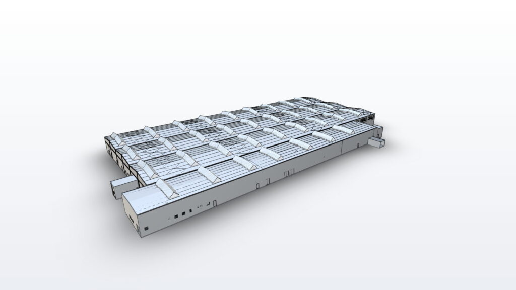
| As-built model | IFC, RVT | Where planning happens in 3D and heights have to be carried along |
| Point cloud | E57, RCP | The reference for re-measuring, including questions nobody had asked at the time of the survey |
| Area schedule | XLSX | Hall, usable and circulation areas to DIN 277 |
Which level of detail makes sense per area is settled beforehand and not ordered across the board. A hall in coarse detail with two precisely captured connection areas is the normal case and considerably cheaper than “everything as accurate as possible”. The term for this is level of information need.
Where our service ends
We capture and evaluate. The planning itself — material flow, cycle times, area required per process step, variants — rests with you or your factory planner. That boundary is stated here explicitly because it regularly blurs in tenders: a survey practice offering material flow planning is either something other than a survey practice, or it is underestimating the task.
What we can do for it: hand the data over so that no rework is needed in your planning system. That includes a test import on one area before the whole hall is evaluated — the same procedure as with the CAFM data handover, and for the same reason.
Further reading
- 3D laser scanning – the capture, while production runs and without shutdown
- 2D as-built plans – the actual layout as a drawing, with axes and dimensions
- MEP modelling – the media in the existing facility: compressed air, power, ventilation
- Industry and plant engineering – what else comes up in this sector
Frequently asked questions about surveying in production
Does production have to stop for the survey?
No. In mobile mapping we capture on the move, along the routes that are clear anyway. We only need a shutdown where an area is otherwise inaccessible. Shift changes and shutdown periods are favourable, because more routes are then clear — but they are not necessary.
Are the machines captured as well?
Their outlines and space requirement yes, their internals no. For layout planning what counts is the area a machine actually occupies, including its operating and maintenance zone — and that regularly differs from the data sheet. If individual machines are to enter the model as components, that is agreed beforehand, because it determines the evaluation effort.
What happens with obstructed areas?
They are captured as they stand. What lies behind a full rack the scanner does not see, and it is not in the drawing afterwards. Part of scheduling is therefore the question of which areas are decisive for the planning — those are worth clearing beforehand.
Can several halls be joined into one site layout?
Yes, that is the normal case on sites with several buildings. The precondition is georeferencing: all captures then sit in the same horizontal and vertical reference, and the halls stand in the drawing as they stand on the site. Without that reference every hall is right on its own and the site layout is wrong.
In which format do we get the layout?
In the one your planning system reads: DWG or DXF for 2D planning, IFC or RVT for a model, E57 or RCP for the point cloud as a reference. Before the whole hall is evaluated, a test import runs on one area — so a format question surfaces while it is still a correction.
Do you take on the layout planning yourselves?
No. We supply the as-built data; the planning happens with you or your factory planner. What we do for it: prepare the data so that it goes into your planning system without rework.
A hall that is to be replanned?
Send us the hall area, the documents you have and the question your planner wants answered. You will get an assessment of the level of detail needed and what that means for capture and evaluation, before anyone travels out.